


 51 / 72

used to prevent implant fatigue failure [6,12]. A finite element analysis
study has shown, that anterolateral double plating as well as long
stems equalize implant stress distribution, increases construct stiffness
and reduces interfragmentary movements at the fracture gap [13].
Not requiring intraosseous anchorage, cerclage wires are almost
independent from local bone quality [14]. Their force transmission
runs centripetally to the loop, fixing radially displaced fragments.
Cerclages are ideally suited for centripetal fracture reduction and
fracture fixation on the level of the stem, since an intramedullary
splinting is present [15]. Due to the fact that the long bone shaft is not
an idealized round tube, the cerclage effects an uneven pressure
distribution on the bony surface with high pressure values at the
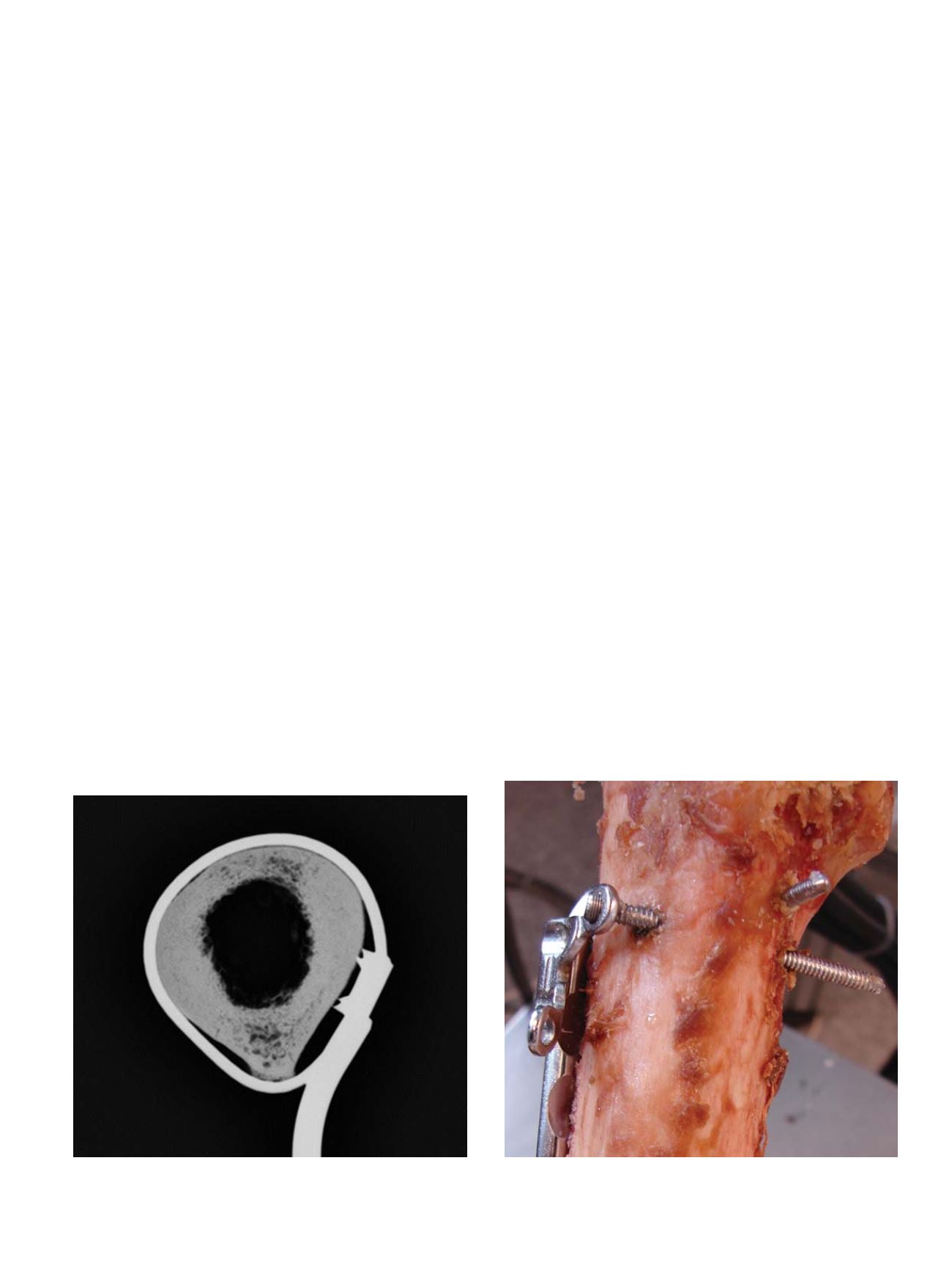
deflection edges [16]. Comparable to the point contact fixation of
modern plating systems the cerclage spans from edge to edge with
non-loaded zones in-between (Figure 1). The contact surface of a
tightened 1.5 mm wire or 1.7 mm cable cerclage ranges from 0.30 to
0.36 mm [14]. In congruently reduced shaft fractures, it is unlikely to
produce a fracture or grade cutting by cerclage tightening, since the
cortex withstands static concentric pressure [16]. Loading the cerclage
fixation revealed no microfracturing at the shaft cortex [16]. The groove
formation, the so called biological loosening of a cerclage [15] is
induced by the micro movement of an already loosened cerclage and
not by the weakness of the cortex itself [15
–
17]. Instead of cortical
bone resorption, a bony ingrowth was observed for well tightened
cerclages [16
–
18]. Noteworthy loss of pretension almost occurs at the
twist. Apart from using a larger wire diameter, pretension could be
influenced by the twisting procedure. Highest pretension is obtained
when the twist is formed under permanent traction by the pliers, the
twist is plastically deformed at the end of the twisting procedure, wire
ends are cut outside the twist and when the twist is bent forward at
the end of the procedure [19]. Backward bending should be avoided,
since 90% of the pretension gets lost throughout this manoeuver.
When plastic deformation of the twist is accomplished, the twisting
procedure has to be stopped before twisting off the wire [19].
Cable cerclages, closed by a crimp achieve higher pretension values
compared to wire cerclages. Looping the wire cerclage twice around
the bone before closure effects pretension values comparable to a cable
cerclage of the same diameter looped once. According to the tackle
principle, the twist is less loaded in the double looped configuration
and a higher amount of travel is needed to provoke loosening of the
cerclage [20]. Ogden proposed a plating construct with cerclage
fixation on the level of the stem and bicortical fixation in the opposite
fracture fragment [21]. Clinical results of this construct exhibited an
overall complication rate of 30% [21] comparable to the failure rate of
allograft struts (24%) placed on the lateral and anterior aspect of the
long bone shaft and fixed by cerclages [22]. If load is applied in axial
direction and torsion, the bone slides under the cerclage [14] if it is not
maintained by the interdigitation of the fracture fragments. To add
stability in axial direction and torsion, cerclage-plate constructs should
be combined with locking screws [5,14].
Screws could be either placed monocortically or bicortically within
the narrow bone corridor lateral to the prosthesis stem. Tangential
intracortical screw placement which reduces fixation strength has to
be avoided during bicortical screw insertion [5,23]. In conventional
nonlocking plates, the screw insertion angle could be varied within the
plate hole allowing bicortical screw placement. The fixation principle
of nonlocking screws, requiring a tight frictional coupling at the plate-
bone interface is not suited for osteoporotic bone [24,25]. Multiaxial
locking screws are one solution of this shortcoming [26]. Broader
plates with laterally placed screw holes [6] or attachment plates
shifting the screw entry point to the lateral allow an embracement
configuration of the bicortical locking screws, a very effective way to
enhance fixation stability (Figure 2) [5,27]. Compared to cerclages
combinedwith monocortical locking screws, the shaft embracement of
bicortical locking screws realized by the locking attachment plate
provides superior stability especially in fractures with lacking cortical
support [27].
Under axial compression force, orthogonal to the screw shaft axis,
monocortical and bicortical locking screws of the same diameter
achieve comparable fixation strength [14]. In both, most of the load is
transferred at the near cortical hole. An ovoid enlargement of the near
cortical hole and a longitudinal fissure of the near cortex was observed
during failure. Since the fissure is located below the osteosynthesis
plate, it could not be detected on conventional radiographs. Detection
of the ovoid hole enlargement on radiographs is sometimes possible
by meticulous analysis [14]. The neutralization of torsional forces
requires bicortical fixation in both, the proximal and the distal fracture
fragment [14].
Fig. 1.
Cerclages, being deflected at the edges of the bone and providing a point
contact fixation with non-contact zones in-between.
Fig. 2.
Plates, shifting the screw entry point more laterally and allowing an embrace-
ment configuration of the locking screws around the intramedullary implant.
M. Lenz et al. / Injury, Int. J. Care Injured 47S2 (2016) S44
–
S50
S45